Construction
1/2 in square aluminum stock was purchased and used for the torque arm and column components of the assembly. The stock was cut with a band saw to the proper lengths for each of the parts. Once the lengths of all components were cut to satisfactory lengths, the features were machined to each specific part. The column was drilled and tapped at one end so that a bolt can be used to fasten it to the torque arm. The torque arm needed a hole at the end opposite of the torque motor that the bolt can go through to the colum. This hole with be tapered so that the bolt sits flush with the top of the torque arm. The torque arm also needed to have small rounds to fit on the NPT piping of the air motor.
The mount was made using a 7x4x0.5 aluminum angle. The aluminum angle was cut in half to become the front and back pieces of the mount. The two halves of the air motor mount were then bored with a boreing bar. Two holes were also drilled into the bottom of both pieces of angle so it can be bolted to the rig plate.
A small mount for the load cell was machined from extra aluminum that was cut from the base of the aluminum angle used for the motor mount. the part has a hole in the middle of it for the load cell. A pathway will be made for the load cell wires to feed through to the digital readout. The fit is snug enough that a set screw is not needed.
Manufacturing Issues
During the construction of the torque measuring device, a myriad of manufacturing issues arose. These issues ranged from simple problems that were quickly fixed to large problems that took extra time to deal with.
The torque arm and 4 in connection piece created an interesting issue. A slight round was necessary in both parts so that they snuggly fit around the NPT piping on the top face of the air motor. The process of creating this round was an issue. It was necessary to use an end mill and slightly touch the edge of the parts till the proper depth round was created. A round that was not too deep as to cause structural issues later down the line, but large enough to create a close fit. These rounds can be seen in the pictures below.
Working on the mount was an issue all on its own. The mount was made from a 7x4x0.5 aluminum angle. Due to the shape and size of this specific angle, fixing it to be machined was difficult every time. Starting with cutting it into two pieces, which was done by the ban saw, creating a non-straight line cut and having to mill it with half the part hanging free and not securely clamped. This caused minor issues to the speed of making the part. Due to the mounting issue, the holes in the mount were made with a boring head on the mill instead of the initial plan of using the lathe to drill the holes. This made the holes take 3 times as long as estimated.
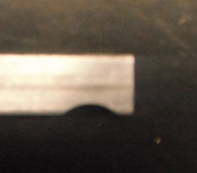
When manufacturing the mount to hold the air motor, a design flaw was found. The back half of the mount was not concentric to the front. The original mount design was made for a concentric line through both the front and back mount. This had to be changed before the mount holes could be bored. Quick measurements were taken to find the centerline of the back face of the air motor. These measurements were taken while the air motor was in the stock motor mount. Due to this, the measurements were off when put into the new mount. This problem was quickly fixed by adding a spacer under the back mount made of spare aluminum. With this fix, the front and back mounts fit around the air motor as originally intended. The small aluminum spacer can be seen in the pictures below. On the left is a close up while on the right is the entire mount/motor setup.
There is a chance of interference occurring once the assembly is fully put together. This means that the parts move or vibrate in a way that was previously thought to be negligible or not even considered until fully assembled. This can lead to minor or major manufacturing issues depending upon the amount of interference preset
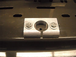
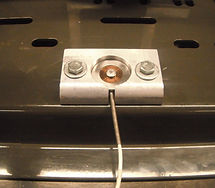
A need for a load cell mount was a manufacturing issue. The original design was meant to have the load cell attached to the rig permanently. This design was altered when Greg Layman offered a load cell and digital readout that was already in the possession of the MET department. Taking into account the new parts, a mount was needed for the load cell. The mount is needed so that the MET department can take the load cell for another project if necessary. The mount serves as the positioning for the load cell. The mount will be permanently fixed to the rig plate in the proper positioning so that the load cell can be added or removed from the rig when needed. Below there are three pictures of the load cell mount.
From left to right: Load cell mount bolted to plate, load cell in the load cell mount, and load cell under column when funcitoning.